This is a standards document that I drew up for a web services project that my team was working on. You will notice that the diagrams are done at a very high overview level.
The document below can be viewed as my personal approach to how I prefered the UML diagrams to be done. Some of this might not be 100% correct due to limitation of the tool but it will give the team a standard and any standard is always better than no standard.
Download the UML Class Diagram Standards document.
Element Containers
Class with detail
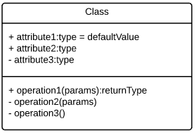
This container is to be used when displaying the members of a class. The top section of the container is used for attributes (fields and properties) The section below it is used to display the method signatures. The order of the signature is not enforced. You can define name : type or type : name. As long as its consistent within the diagram for all signatures fields and methods. Usually we only indicate members up to the public level but to indicate additional access modifiers the following must be used.
+ Public
– Private
# Protected
# Protected (Overridable)
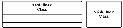
Static
Types
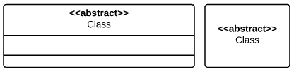
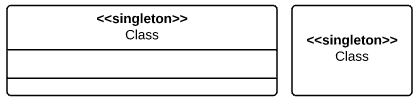
Class
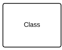
When doing a high level diagram or when the members are not needed on the diagram one can use this type of container for a class. It is simply used to communicate a relationship.
Active Class with detail.
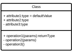
The active class container indicates that, when the class is instantiated it would be in control of its own execution and will be running on its own thread – separate from the rest of the objects on the diagram.
An example of such a class is a web service class that might be on the diagram. Normally the active class will have a double line border. It all depends on the UML tool being used.
Active Class
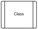
When working at a high level or when the detail of the active class is not required the follow container can be used.
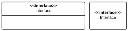
Interface
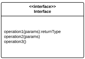
Use the following container when describing the members of an interface. A interface cannot have access modifiers as all members have to be public. Note the stereotyping <<interface>> tag applied to the top of the container.
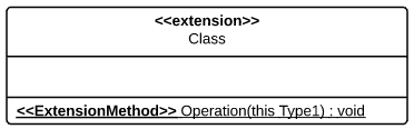
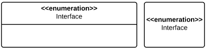
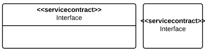
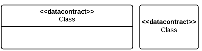
Stereo Typing
To be able to communicate additional type information we can use stereo typing.
Stereo typing is used to refine the meaning of a model element by adding the following ‘<<description>>’ tags above the element name. Example – One of the most common known stereo types is that of <<Interface>>
Here follows a list of the stereo types that we will support.
Inheritance
Inheritance should always be depicted in a top down manner. The derived types must always be below the super class.
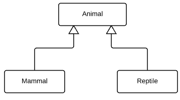
Inheritance are always depicted using solid lines and arrow heads. Arrow heads always point in the direction of the super class. Do not combine lines from derived types rather keep them separate.
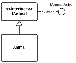
When inheriting from an interface use the same method to indicate inheritance as with classes when the interface and its members are on the document. Note that inherited members are not duplicated in derived types.
This notation is only allowed with interfaces in high level overviews where one wants to show relationships that the lollypop notation cannot provide.
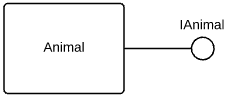
When inheriting from an interface use the lollipop notation to indicate inheritance when: 1. The interface with its members are not defined on the diagram. 2. The lines to the Interface on the diagram would make the diagram look to complex. Note that with this notation the inheritance line comes of the side of the container.
Composition, Aggregation and Usage should be displayed by connecting to the sides of the UML containers.
Composition
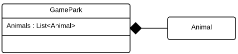
Composition depicts ownership by using a solid diamond. The solid diamond is connected to the side of the owner element. The owner is in control of the existence and lifetime of the other element. If it created it, it is responsible to destroy it. This is a one way relationship and only one of the elements can be the owner. When inheritance takes place composition is only indicated at the highest level and not in derived types.
Aggregation
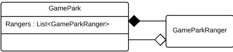
Aggregation is depicted using a clear diamond in the direction of the element that holds the reference and usually connects to the side of the element. Aggregation indicates relationships, not ownership. It is possible to have relationship references in both directions. When inheritance takes place aggregation is only indicated at the highest level and not in derived types.
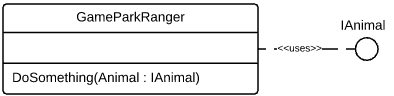
Usage
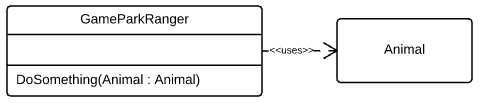
Usage is depicted using a dashed line with an open arrow in the direction of the class being used. Usage indicates that either the type or instance of class is going to be used for the duration of a method.
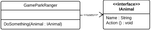
Variations exist for the usage with an interface. Note the difference between aggregation and usage is that usage does not maintain a reference to the other element for the lifetime of the object.
Relationships to Enumerations always use usage when inheritance takes place usage is only indicated at the highest level and not in derived types.
Normally this is depicted with a solid line and and a half circle but due to * Lucidcharts not supporting it I suggest we use the following notation.
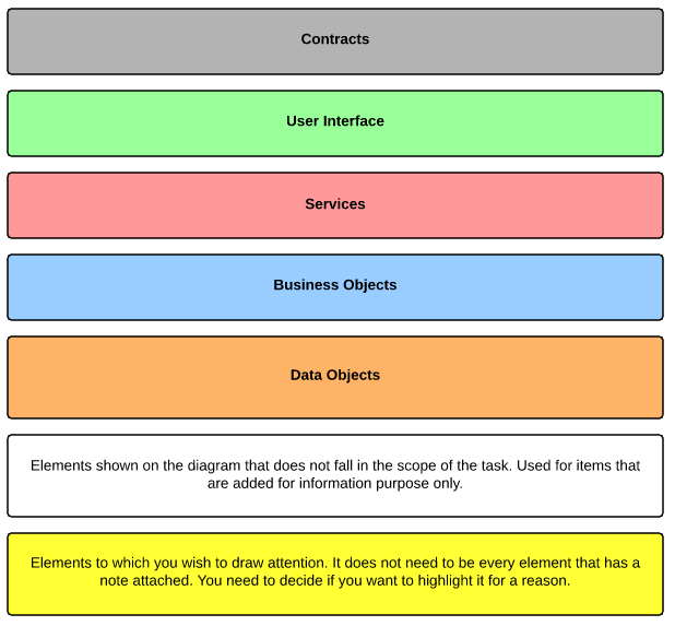
Colour Usage
Please use the following colour guide where possible and supply a legend at the top right of your diagram with the assembly name or grouping description inside the colour block.
Colours must indicate which entities are grouped together in an assembly. If assemblies have not been identified or if no additional colours are needed then please use the example below.
In situations where more colours are needed for a diagram feel free to use your own colours just be sure to supply a legend at the top right of your diagram.
Example
Below is an high level example of what a uml class diagram should look like when the standards have been followed.
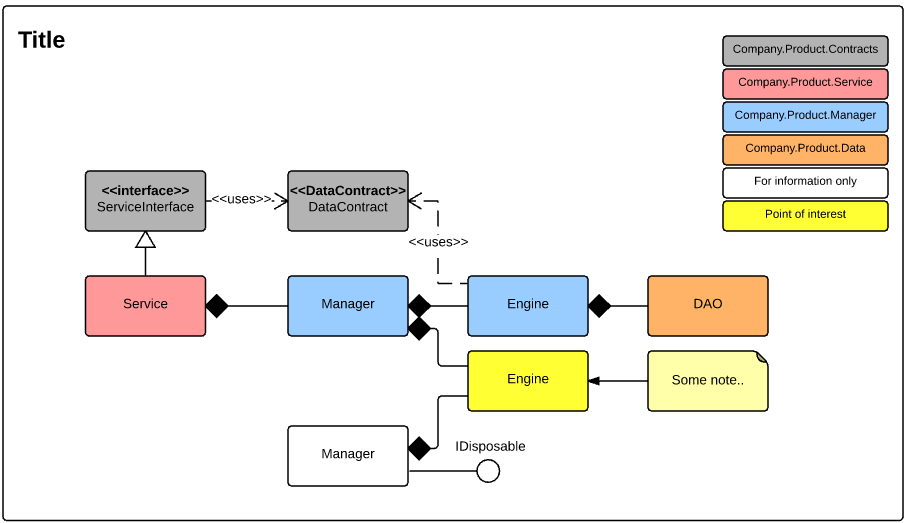
Normally the Service and Data Contracts are the only containers in the diagram that are required to have detail.
We created our diagrams with Lucidcharts. The diagram tool has a nice feature set and is good enough for most cases but we found at the time that it suffered when the diagrams become very large and complex. The UI was intelligent enough to pick up when a document didn’t save due to LAG and we did not loose any work as a result. Luckily with SOA the service design is not complex and does not require large the class design complexities of desktop applications.